Thank you!
Our employee will process your data and will contact you shortly.
We value each of our clients and are always glad to see you
on our website.

Railway application Tomographic 2.6 is designed for acceptance and operational testing of the welded rail joints on track or in the rail-welding machine. This application is intended to handle joints performed by the method of alumino-thermal or electric-contact weld in accordance with RZD Industry Standard 1.11.003-2009. It is applied also for testing of point frog seams under technical requirements of the RZD Industry Standard 1.11.007-2009. It can be used for performance of sample/confirmatory nondestructive testing (secondary testing). It is recommended by OJSC RZD for application in the 1520 gauge space being the modern diagnostic and monitoring tool, which ensures testing of welded joints across the whole rail section, including head, web and base.
Automation of testing and protocol generation processes is achieved due to application of coordinate devices «Tandem», «Videoscop», «Slider М3» and «Slider М4» (stationary version of Slider M3 for rail-welding machine).
Advantages of the Tomographic 2.6 application:
Testing performance procedure is monitored by means of coordinate device «Slider М3» and «Tandem», when testing is carried our en route, or «Slider М4» - in conditions of the rail-welding machine. Equipment follows up coordinates of the probe movement taking into account existence of acoustic contact.
On completion of testing, report is generated, where useful data on testing parameters, sweep scans, visual presentation of flaw location and coordinates is stored. Report can be viewed both on the instrument screen and by means of a computer.
«Slider М3»
Mechanical system of 2D coordinate referencing. Such device is applied together with flaw detector UD4-ТМ/UD4-Т. It is used to determine location of piezoelectric probe on the tested object, as well as to follow up its movement path. System makes it possible to monitor the completeness of testing, to store in real time location coordinates of the detected flaws, as well as to display them graphically and to evaluate their hazard level.
«Slider М3» is applied en route for diagnostics of seams of alumino-thermal or electric-contact weld. It is used also during performance of secondary testing. Prior to carry out works, device is installed on the rail head and is secured by means of magnets.
Advantages of «Slider М3» system:
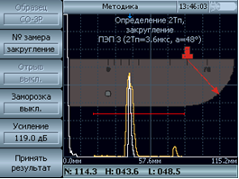
Below A-scan on the screen, B(x)-scan representing an aggregate image of the series of B-scans is displayed. B-scans are superposed taking into account the direction of scanning in relation to joint. In the bottom part of screen, C(x,z)-scan is displayed, which is broken down into cells.
Each cell of C(x,z)-scan corresponds with straight or broken line on the B(x)-scan. During detection of echo-signals exceeding threshold of the automatic flaw signaling unit (monitor), cells are colored green, white, orange or red. Color gradation indicates increase of signal amplitude in respective cell.
«Slider М4»
It is an upgraded version of «Slider-М3» intended for use in conditions of the rail-welding machine. It eliminates the necessity for device to be installed on a rail. It also supports possibility of the bottom part of rail base in the form of B- and C-scans.
«Slider М4» is a scanning device mounted on a stationary frame to be secured to the floor. When requirements of the RZD Industry Standard 1.11.003-2009 governing the testing of joints are complied with, the permissible zone of weld stop amounts to 320 mm in longitudinal direction and 40 mm in transverse direction. Diagnostic results are recorded across the whole rail section due to opportunity of crossbar rotation around axes.
Advantages of «Slider М4» system:
Rail flaw detector Tomographic UD4-ТМ is equipped with GPS-receiver, which allows position of every joint to be referenced to the site coordinates. In this case, operator’s functions are limited by correct installation of scanners, selection of respective application from the package of built-in software and “coloring” of the selected area of testing on the device screen. Rendering on the display is performed in real time mode, which makes it possible to define locations of defective areas, as well as areas, where there is no contact of PEP with rail. During testing, it is possible to connect device with additional scanners of Tandem and Videoscop models.
«Videoscop»
This device represents portable videocamera mounted on the telescopic tripod. It is intended for detection of flaws under 53.1 code without removal of fish bars, as well as under 69 code without application of mirrors. Videoscanner is applied during sample visual testing of track superstructure elements and rail bolt holes.
Testing by this device allows defective area images with actual sizes to be included in final reports. Videoscanner is connected by means “Scanner” connector on the side panel of flaw detector. It can operate in line with the main channel of nondestructive testing (eddy-current, ultrasonic, electro-magnetic and acoustic, etc.). In addition, image is projected on the UD4-ТМ display.
«Tandem»
It represents the scanning carriage performing testing of the running surface of transverse welded joint. Process is carried out by means of two angle piezoelectric probes (45˚) under mirror method.
Application of the UD4-ТМ flaw detector in conjunction with “Tandem” device makes it possible to scan objects with required scanning index and storing of flaw location coordinates in memory. Also, instrument allows plotting in real time of B-scan of transverse seam in the area of head and web and its projection in the base. Thereby, time of testing is reduced and it becomes possible to decode data from the instrument.
«NDT operator AWS»
It is PC software required to transmit databases of test reports from the NDT instrument into computer. It is used also for preparation and printing of test results with images of detected flaws. Besides, software makes it possible to maintain databases on the state of tested objects.